Before we start the build instructions, we would like to say a big thankyou for supporting our shop.
Also, you are about to build a relatively new concept in antenna design. Not that an End Fed Half Wave (EFHW) is unique or a Common Mode Choke (CMC). But the combination of both on a single PCB is.
The idea behind this PCB is to have your EFHW antenna isolated from your coax. Unlike most other EFHW designs where this is not the case. Other designs (including some of ours) use your coax as a counterpoise.
This means the coax is part of the antenna system so you don't really know what's at the antenna unless you put a common mode chole about 0.05l below the EFHW transformer.
With this kit your coax is isolated from the antenna. If you have a CMC just before the transceiver the coax is also isolated from the transceiver eliminating noise picked up on the outside of the coax when it enters your shack. Which is great.
The flip side of this design is you must have a counterpoise on the antenna itself. We will get into that a little later.
So lets start.
Difficulty
This is not an absolute beginner kit because adding a T240-43 to the board can be fiddly, this is the only part of the build which is not as easy as our other kits to get right.
Also take special care when drilling the case, I suggest the counterpoise hole is drilled at least halfway down the box towards the SO239 connector. This is to keep the counterpoise clear of the antenna wire.
We also recommend using a compensation coil on your antenna wire about 2m meters from the antenna start point. This will help pull the higher bands down to resonance. You can download a former for this from our Thingyverse page. Or you can put five or six turns of antenna wire around a 25mm pipe 2m from to antenna start point. It will work from the end of the antenna as well, if like me you forget to put one in place when you install the antenna wire.
Other than the two points above this is no harder to build than our other EFHW kits. The build time should take about 1-2 hours, if you are taking it easy and drinking tea or coffee.
Drilling
The first thing to do is to drill the case. You will need to drill 5mm holes for the antenna and counterpoise connections. The box supplied has flanges to attach the case to a post or suitable support.
For drill bits, 3mm, 4mm, 5mm, 12mm and step drill are what you really need to make things super simple.
If you have a 3d printer and would like to download the drill template drop us a note and we will provide you with the STL file or use this Thingiverse template. It will help you out a lot.
If you do not have a 3d printer mark where you want to put the components with a sharpie. To do this I would drill the larger hole 1st put the SO239 in the hole, then mark out where the smaller bolt holes go, then drill them.
Using a 3mm drill and the template place the template onto the case and drill as per the image below.

Template in place drill all 6 holes. This is one pilot hole for the SO239, four holes for the SO239 screws and a breather hole for the enclosure (if you want one).

Turn the enclosure around. Use the template to drill one hole is you are using the eye or putting the antenna connection on the top.

Put the template on its side and drill, along one side of the enclosure (take note of where the counterpoise solder pad is on the PCB) and drill holes in the middle of the case where you want the counterpoise.

Attach the S0239 using the screws and nuts provided. Put the longer screws 12mm in the top two holes, it makes the final build easier.

Thats the case drilled.
Building the transformer
It’s entirely up to you how you want to wind the transformer.
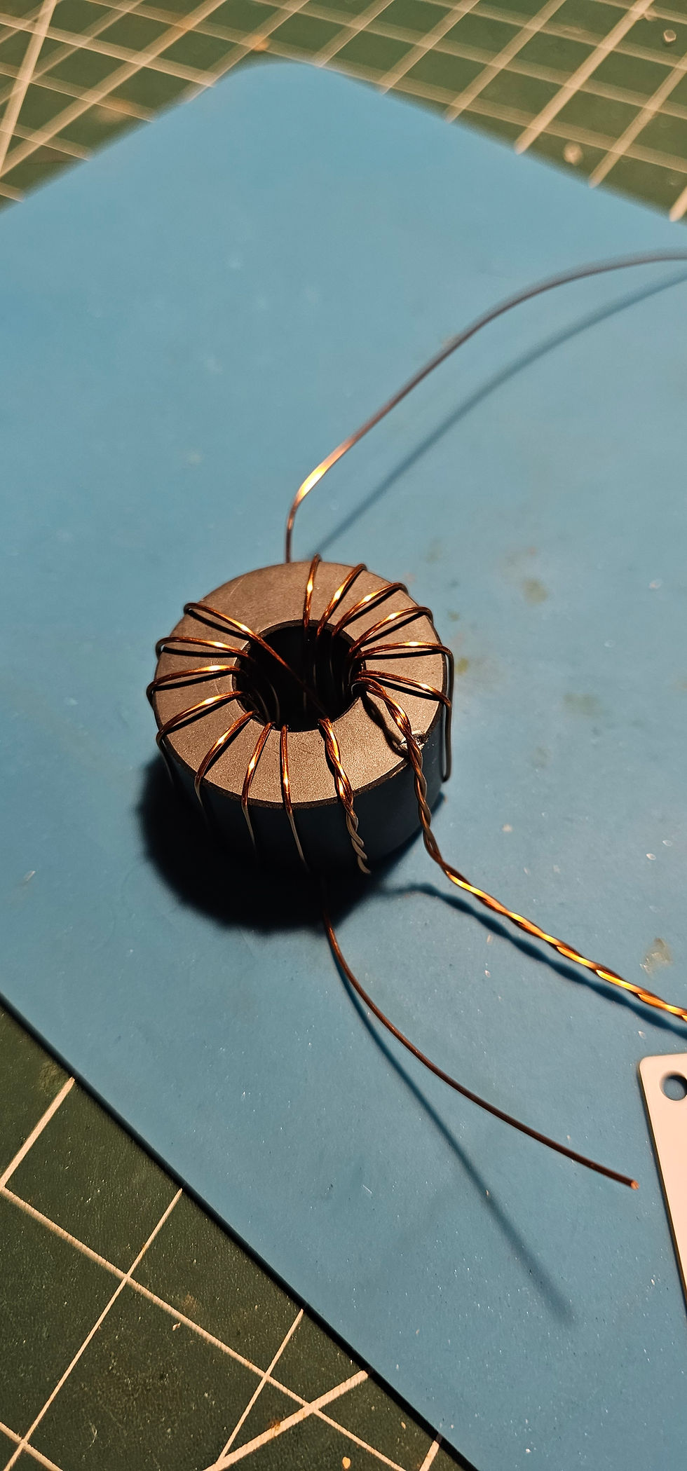
In this example it’s a 56:1 EFHW that’s 15 primary and 2 secondary windings. This works very well with a 1002 core. If you want to create an autotransformer or other type of winding your build will differ from mine. You will see a small chip in the toroid below, I dropped it. Be careful.
When you have would the transformer put it on top of the PCB. You will need to trim the wires going through the PCB, do this now. You need about 2 to 3 mm of clearly visible enamelled wire on the reverse side of the PCB.

It should look something like this when trimmed.

This is a good time to clean off the last part of the wire you are going to solder to the PCB. I find a file, knife, lighter or soldering iron is ok to do this job.
Building the choke
It’s also entirely up to you how you want to wind the CMC. I normally do 12 turns of coax through the 240-43 toroid or 8 through the 2631101902 toroid. The one thing I would say is ensure you have enough coax on each side of the toroid to be to solder to the PCB pads and SO239.
To wind a 240-43 this is what you need todo. First get the parts you need.

Then attach one end.

Wind 5 turns, then across the middle that's 6, then 6 more.

Just ensure you end up starting on one side and ending on the other. Or its going to be a nightmare for you to make all the solder joints.
If you have selected the 100w options the choke is wound differently. See below.
Each turn through the Middle of the barrel toroid counts as one turn.

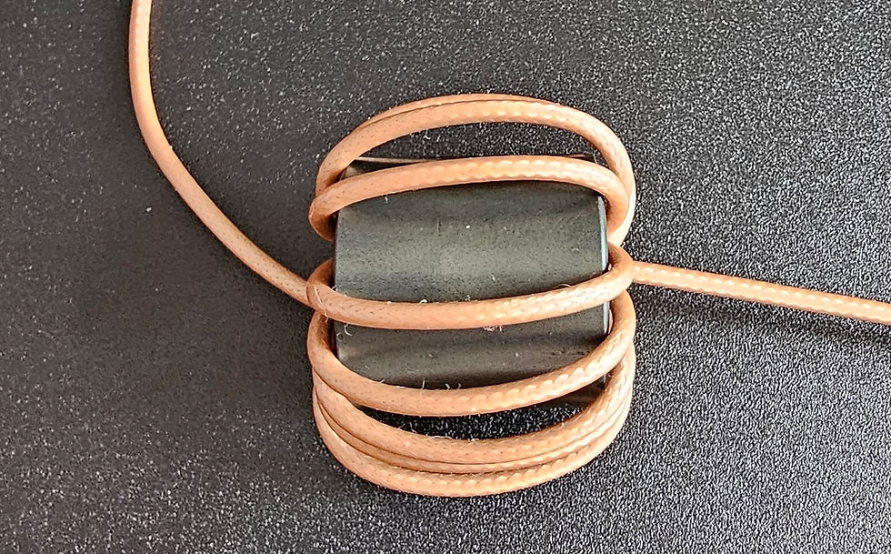
You make this choke by possing the provided RG316 though the core 8 or 9 times. Do not pull the coax tight.
Final assembly
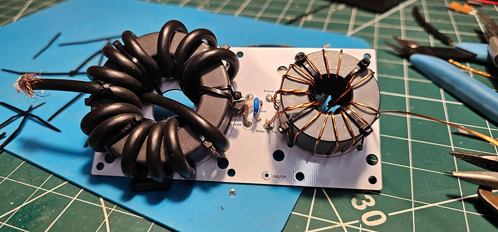
Next step. I would then suggest you solder the transformer and capacitor in place. Then secure with the transformer with the provided cable ties.
Then you can attach one side of the Common Mode Choke to the PCB.
You’re going to strip some of coax outer insulation and trim to length the braid, and centre to create a Y in the coax. The inner centre conductor going left into the Centre of Coax pad and the outer going onto the Coax shield pad. Do not short out the centre and braid. If you do your antenna will not work. You will see on the picture I have then soldered the coax in place.

Also when soldering ensure the soder flows to both sides of the PCB. The tracks are on both sides to ensure it will handle 400w SSB. I would suggest soldering from the bottom of the PCB. Then if needed the top. However a good soldering iron and flux solder should do the job in one go.
Now this is the tricky part if you have selected the T240 and RG58 option.
When you wound your choke (providing you have done this the way I have). You will have one end of the coax on one side of the toroid and the other end on the other side.
It’s good to have it this way, it means you have a natural layout for attaching the coax to the PCB and SO239. In the image above you will see I have used the lower part of the Coax for the PCB.
Now cable tie down the toroid, then place the PCB in the enclosure with the transformer and toroid in situ.

With what is left of the coax I suggest you cut it just after the enclosure, mark back to about 5mm past the outer diameter of the toroid.
You’re now going to strip the outer insulation from coax and make a T with the shield going left right and the centre going forward. You’re going to need to eyeball how far back you strip the centre insulator. Strip it back and check it all fits. You are looking for a fit where the coax centre goes into the SO239 connector.

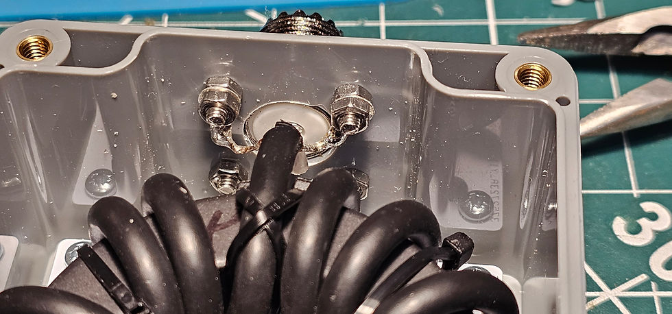
Now you will need to solder the centre of the coax into the SO239. You may find it easier to tin the centre of the coax and pre-solder the SO239 and just re-heat and push the centre in place.
Either way you should not have the centre in place. Now offer up the shield T to the 12mm screws. Trim the shield and solder on the solder tabs. Now you can bolt the tabs into place.
The last thing you need to do is solder on the antenna and counterpoise solder tabs in place and put the supplied M5x16mm bolts through the solder tab out through the enclosure holed you drilled and then tighten then up with the supplied washers and nuts.
The 100w RG316 version is a little different. You will still solder the Coax to the board (image taken from our 9:1 build page).

However, at the SO239 end you will attache a single solder luf to the coax.

Which is soldered in place.
Also screw the PCB in place with the provided M3 screws.
Your done!

If you want to secure the nuts and bolts from the weather and also the SO239 you could use a glue gun. Also, for the coax at the capacitor side you could insulate that with glue or nail varnish.
This is what I have done on my build.

It’s at this point you may have realised you drilled the 5mm holes in the wrong place. So hopefully you read these instructions 1st.
Testing
This is simple to test now if you have a VNA of Antenna Analyser. You can place a 2.4kohm transistor from the antenna to the counterpoise and scan from 1mhz to 30mhz. You will see the sweep lower at around 3mhz then up a bit around 28mhz. Depending on the core the sweep will be different. This is however of no real use, other than to prove the transformer works.
Please note because you have a combined transformer and common mode choke the SWR on the sweep will be slightly higher than a transformer on its own.
Tuning
To tune is easy. Cut antenna wire and a counterpoise to the suggested lengths. Here is a brief table of some suggested wire lengths.
Frequency MHZ | Wire Velocity Factor | Half Wave | Counterpoise |
3.5 | 1 | 40.86 | 4.25 |
7 | 1 | 20.43 | 2.12 |
14 | 1 | 10.21 | 1.06 |
21.35 | 1 | 6.70 | 0.70 |
28.5 | 1 | 5.02 | 0.52 |
The key here is the counterpoise, this MUST be added to this antenna for it to work. Your coax will be isolated from the EFHW transformer, therefore your coax will not be a counterpoise.
Put your antenna analyser on the EFHW-CMC and the wire up in the air where its going to be. Tune for a low SWR. Or low SWR and Resonance. The second being more difficult and sometimes impossible. But a low SWR is a must at the bottom of the lowest band of use. Like 7.000 mhz.
If you want to see what happens to an EFHW without a counterpoise remove it after you have tuned your antenna and seep it again.
We will put some notes on alternate tuning methods on the blog soon.
Comments